Demodulation Techniques Ppt
4-11 to 4-15. EE4512 Analog and Digital Communications Chapter 5 Chapter 5 Digital Bandpass Modulation and Demodulation Techniques Binary Amplitude Shift Keying Pages 212-219.
Ece 489 Lab 5 Phase Modulation And Constellations
Lecture notes on.
Demodulation techniques ppt. There are a number of techniques that can be used to demodulate AM signals. Requires a replica carrier wave of the same frequency and phase at the receiver The received signal and replica carrier are cross-correlated Also known as synchronous demodulation Carrier recovery methods Using PLL to recover the carrier phase and frequency from the transmitted pilot. Noise in the system external noise and circuit noise reduces the signal-to-noise SN ratio at the receiver Rx input and hence reduces the.
After demodulation we get the original modulating signal at the demodulation output. If we were to implement every possible combination of demodulation algorithm carrier-recovery technique and clock regeneration as a distinct model the combinatorial explosion of different models would become unmanageable. Demolition of Buildings Ppt - Free download as Powerpoint Presentation ppt pptx PDF File pdf Text File txt or view presentation slides online.
Connect clock signal 64KHz from the transmitter to the receiver using coaxial cable 23. Diode rectifier envelope detector. This demodulator contains a square law device and low pass filter.
This process is used in the receivers to recover the original signal coming from the sender end in modulating form. 2 π f c t We know that the mathematical relationship between the input and the output of square law device is. 2 Slide 17 Linearized Model for PLL Slide 18 Proof PLL is a Demod for FM Slide 19 Comments on PLL Performance Slide 20 FM PLL vs.
Connect transmitter clock to the timing circuit. Nov 16 2021 - Chapter - Amplitude Modulation and Demodulation PPT ADC Semester Engineering Computer Science Engineering CSE Notes EduRev is made by best teachers of Computer Science Engineering CSE. Keep CRO in dual mode.
Connect PCM signal to the demodulator input S-P shift register from the PCM modulator with the help of coaxial cable supplied with the trainer 22. This form of detector is the simplest form only requiring a single diode and a couple of other low cost components. PSK technique is widely used for wireless LANs bio-metric contactless operations along with RFID and Bluetooth communications.
DIGITAL MODULATION TECHNIQUES. FM demodulator or detector is basically a frequency to amplitude converter. This document is highly rated by Computer Science Engineering CSE students and has been viewed 3388 times.
It is expected to convert the frequency variations in FM wave at its input into amplitude variations at its. FM Demodulator Classification Coherent Non-coherent A coherent detector has two inputsone for a reference signal such as the synchronized oscillator signal and one. Introduction to modulation and demodulation 1.
Civil engineering report ppt. Winner of the Standing Ovation Award for Best PowerPoint Templates from Presentations Magazine. Introduction to Digital Modulation Demodulation techniques - Free download as Powerpoint Presentation ppt PDF File pdf Text File txt or view presentation slides online.
AMPLITUDE SHIFT KEYING In ASK the amplitude of the signal is changed in response to information and all else is kept fixed Bit 1 is transmitted by a signal of one particular amplitude. All modulation techniques involve operation on one or more of the three fundamental frequency domain parameters. Digital Modulation and Demodulation FSKPSKBPSKQPSK Techniques.
Outline FM Demodulation Techniques. Demodulation 1 ¾Coherent demodulation. Describe fm demodulation circuit operation for the phase-shift and gated-beam discriminators and the ratio-detector demodulator.
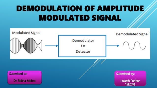
Demodulation The purpose of a communication system is to transfer information from a source to a destination. Demodulation is defined as extracting the original information-carrying signal from a modulated carrier wave. Different types are used in different applications to suit their performance and cost.
Tasks and these techniques can be used across a wide range of modulation formats and demodulation schemes. Slide 13 Phase-Locked Loop Demodulator Slide 14 PLL Analysis Slide 15 PLL Analysis cont. Demodulation of FM Waves The demodulation process of FM waves is exactly opposite to that of the frequency modulation.
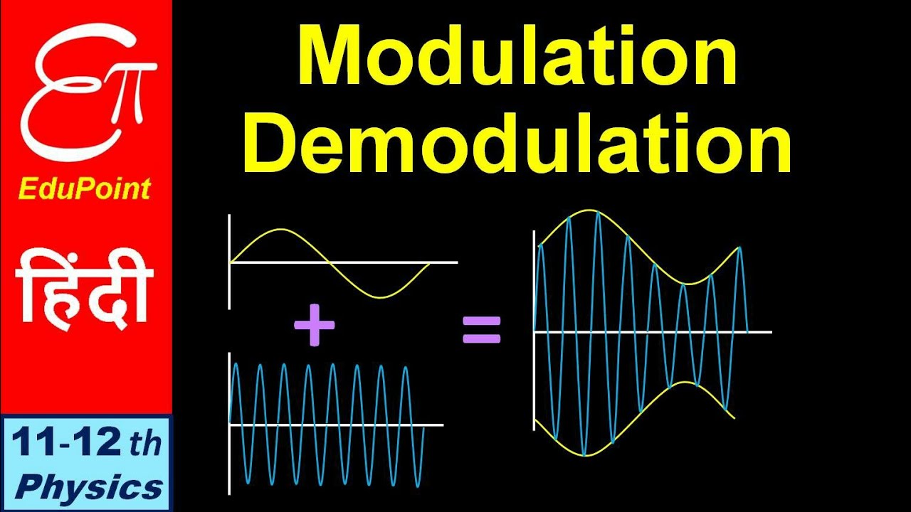
In practice problems arise in baseband transmissions the major cases being. A basic amplitude-modulated double-sideband full carrier signal is obtained by mixing a modulating signal y m t at a modulation index M and frequency ω m 2πf m with a carrier signal y c t with for the sake of brevity unity amplitude phase and frequency ω c 2πf c such that 1 In the time domain this process is shown in Figure 1a where the minimum and the. Worlds Best PowerPoint Templates - CrystalGraphics offers more PowerPoint templates than anyone else in the world with over 4 million to choose from.
To transmit 0we change the amplitude keeping the frequency constant. 1 Slide 16 PLL Analysis cont. Amplitude frequency and phase.
INTRODUCTION In chapters 1 and 2 you studied how to apply intelligence modulation to an rf-carrier wave. Describe phase demodulation circuit operation for the peak low-pass filter and conversion detectors. EEE2009EEE2009 CommunicationsCommunications Contents Introduction to Communication Systems Analogue Modulation AM DSBSC VSB SSB FM PM Narrow band FM PLL Demodulators and FLL Loops Sampling Systems Time and Frequency Division multiplexing systems Nyquist Principle PAM PPM.
Phase Shift Keying PSK is the digital modulation technique in which the phase of the carrier signal is changed by varying the sine and cosine inputs at a particular time. We can say that its function is opposite to that of modulation process. Theyll give your presentations a professional memorable appearance - the kind of sophisticated look that todays audiences expect.
A demodulator is an electronic circuit that is mainly used to recover the information content from the modulated carrier wave. V 1 t A c 1 k a m t cos. As we have discussed earlier that signal transmission is done by superimposing the signal on a.
FM Demodulation Techniques PLL Updated. The AM wave V 1 t is applied as an input to this demodulator. The standard form of AM wave is.
Coherent demodulation Observe that s SSBtcosω ct mtcos2ω ct m htsinω ctcosω ct 1 2 mt 1 2 mtcos2ω ct 1 2 m htsin2ω ct If we filter φ SSB cosω ct with a LPF we can eliminate the components centered at 2f c and the filter output will be mt Hence any of the coherent demodulation techniques. The AM Signal The AM Spectrum AM Modulation Scheme Square-Law Demodulation Coeherent Demodulation Hands-On Simulation Implementation using the DSK6713 The Simulation Environment The Simulation Environment Real Time Environment GUI SQRT Detector Real Time Coherent Detection Real Time Configurable Carrier Carrier Side Bands X X Modulator Virtual Scope.
Modulation Demodulation Amplitude Frequency Communication System Part 4 In Hindi Youtube
Demodulation Of Am Wave
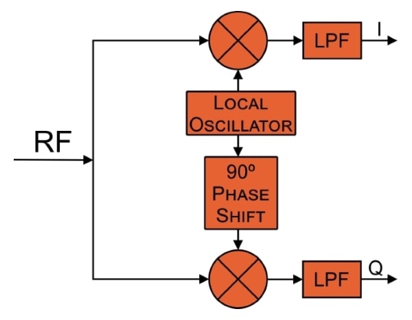
Understanding Quadrature Demodulation Radio Frequency Demodulation Electronics Textbook
Posting Komentar untuk "Demodulation Techniques Ppt"